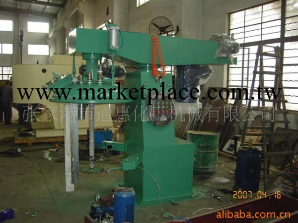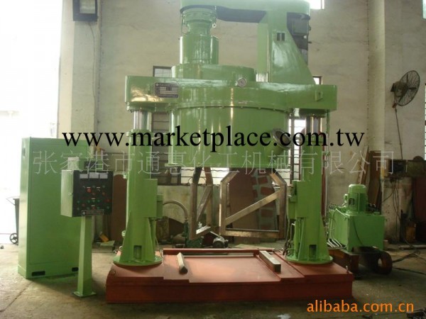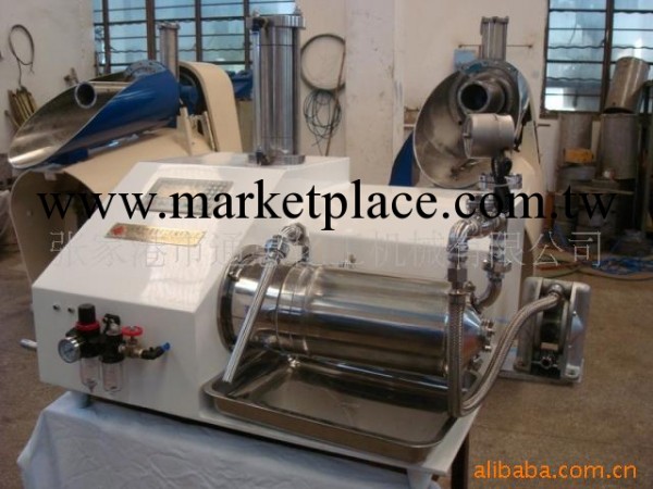

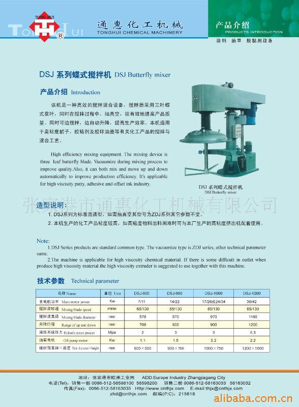
Model:ZSJ-890
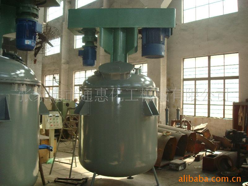
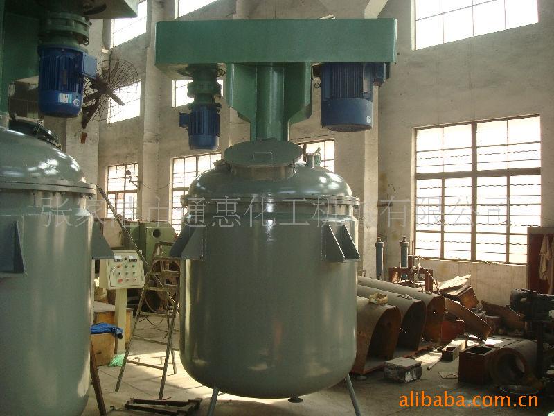
Double Shaft Mixer Machine
instructions
張傢港市通惠化工機械有限公司
ZHANGJIAGANGCITYTonGHUI CHEMICAL MACHINERY CO.,LTD
Catalog
- Summarize………………………………………………..( 1 )
- Main data…………………………………………………( 1 )
- Structure and capability…………………………………..( 1 )
- Installation and debugging………………………….........( 2 )
- Use and maintenance…………………………………....( 2~3 )
Table of Hydraulic pressure component and parts that easily lose………………………………………………………….( 4 )
Attach:
1、 structure diagram…………………………………( 5 )
2、 basic chart………………………………………( 6 )
3、 principle chart of electric machine………. ………( 7 )
1. summarize
Double shaft mixer machine is the new type of high efficient mixer machine. It applies to churning up high viscoidal material, originated at home.
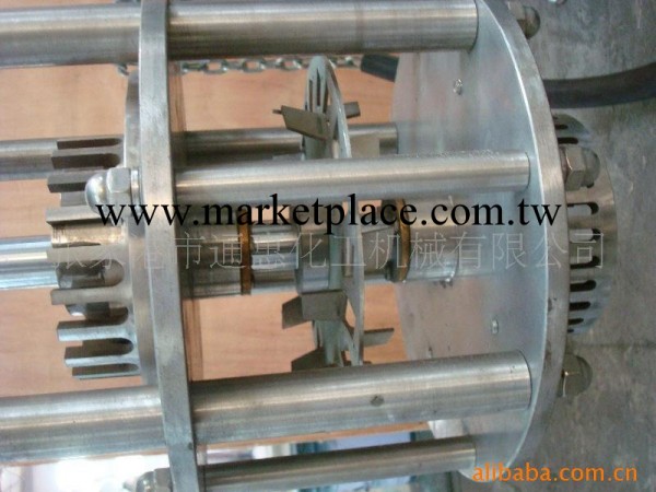
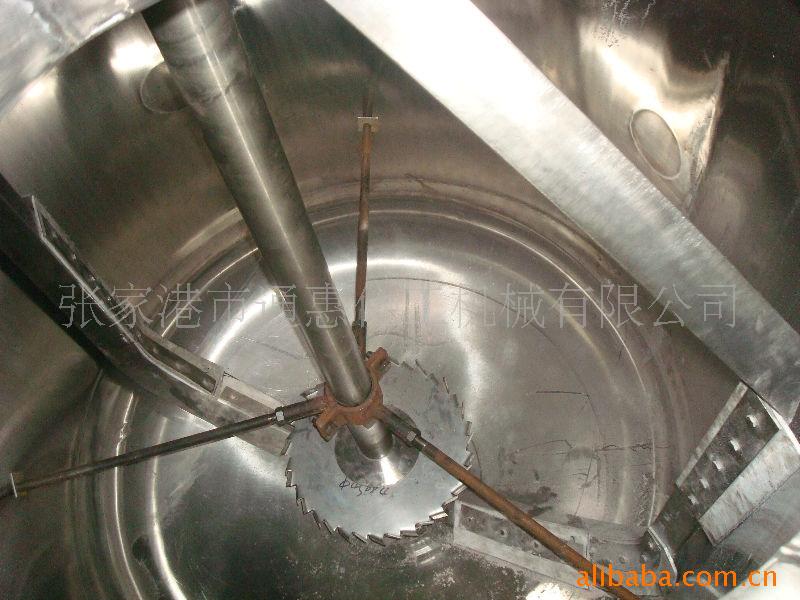
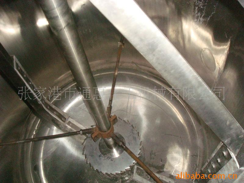
This machine has high speed axis and low speed axis, the mixer of the low speed axis make the material turn up and down in the canister. Collision and cutting are caused by the dentiform lamina of high speed axis and the material, which make congeries damage separate rapidly, blend equably, speed up melting. Plasm pumped when it turns around, and the material in it will reach to blend fully and disperse. It is widely used in the field of chemical products such as dope, printing ink, food, pigment and so on..
2. main data
1. high speed electric machine YB180L-4-37KW,440V×60Hz
2. low speed electric machine YB180L-4-17/26KW,match with XLD8185-11 retarder
3. diameter of dispersive lamina φ280mm
4. diameter of mixer φ860mm
5.rotate speed of high speed axis 0-1440rpm, frequency conversion timing
6. rotate speed of low speed axis 60/120rpm
7. max raise distance 950mm
8. vacuum device vacuum pump XD040, vacuum degree≤-0.08MPa
8. cubage of canister body 500L
9. oil pump electric machine 2.2KW
10. the weight of mainframe ~3000kg
11. size of shape(lengthXwidthXheight) 2695×1300×3400mm
- Structure and capability
Structure: It contains seven sections: hydraulic pressure elevate, wheel box, high speed mixer axis, clamp device, mixer canister, hydraulic pressure system, electric control box
Capability:(1) Stand pole lift smoothly, neatly. It has the protector of overall valve, safe and reliable, and operates conveniently
(2)In the wheel box, low speed axis is brought driver along retarder, then the driven wheel is brought by strap. The high speed axis and electric machine straight joined drive calmly, reliably, compact structure.
(3)Main drive system run smoothly, it has low noise, which are accordance with the standard of environmental protection.
(4)Hydraulic pressure system is match with gear pump, that make the good capability of fluid drive
-1- |
- Erection and commissioning
(A)Erection
(1)The basic device should be obligated the hole and obligated to bury the bolt 5-M20400 (80mm taller than the ground), see the detail of basic dimension chart
(2)Stand pole that mainframe installs should be vertical by the ground.
(3)Oil box installation: capability of explosion protection, it can be located in the explosion district.
(4)Electric control box installation: it adopts starting up directly, occuring little spark. If there is no requirement of fireproofing in the plant, it will be installed directly near the mainframe. If it needs fireproofing and explosion protection in the plant, then it will be installed in the district of non-explosion.
(B)commissioning
1. When the oil box is clean, infusing 20#mechanical oil to the plastic oil up level of 2/3 height.
2. Check clamp between clamp institution and canister
3. Check the degree of tightness of the triangle adhesive tape
4. debugging:
(1) Turn on the power, press raise button(pump electric machine), loose exhaust valve bolt, remove the air then screw it tightly, adjust overfall valve to oil pressure 18kgf/ cm2(1.765MPa)
(2) Press raise button, when the vat raise to the max distance, then stop it, check the location of the oil box, it can’t be less than half of the nether plastic oil level, or it will be supplied oil. Check the leakage in all connective sections and sealed sections, press dro button(electromagnetism smooth valve, make the canister down to the lowest location.
(3) After the the churn-up canister at the right position, fix the adjust bolt on the device.
(4) According to the height of the load, adjust the time relay, confirm the better to-and-pro distance. It is required that the max height of raising guarantee the lamina under the surface of liquid and more than 100mm of the distance of liquid.
5. Use and maintenance
(A)use
(1)Turn on the power, check all the switches, indicator light, button of the control box and voltage.
-2- |
(2)Fix the churn-up canister tightly, make the tight journey close, switch on the second power, choose the high speed movement and low speed movement, then press the button according to the indicator sign. It can operate .
(3)In the course of the operation, if it turns over loading, it will be stopped and check the reasons, when all is right, then continue running.
(4)It should be delivered liquid material first however operate normally or production debugging, when immerge the low speed plasm ,it starts the low speed axis, turn around slowly, then enter the solid material. when all the material is in, then adjust the timing machine to the high speed, and start the high speed axis.
(5)Operate normally, the charge modulus of the canister is 0.7, about 0.35 m3,scilicet the height of the charge is 560mm, according to the condition of the material, it also can reach the eligible products when it cannot start the to-and-pro operation. But when the charge modulus of the canister is more than 0.7 or join the liquid to the surface of churn-up material , it should start the up-to-pro button, which can make the product even quality.
(6)In the course, if it has long time power cut, and it can not start because of the material fall to the increase of normal temperature viscoidal or other reasons such as the deal of solid increases, high viscoidal, overloading, it can lift the plasm above the surface of the liquid, then start the slow speed axis slowly, and the stand pole falls down slowly(manual). When the separated lamina is immerged under the liquid, then start the high speed axis. It can reach the aim of operating normally when the temperature of the material is increasing, the viscoid is falling. And the time of operation is not suitable for long, because of volatilization of solvent.
(7)When after work, stop the machine, turn off the general switchⅢ, lest that the machine should be damaged.
(B)maintenance
1. All transmission part should be often add lube, high speed transmission shaft should be added MoS2—2(2#Li-lubricate fat)once a week, low speed transmission shaft should be added ZL45—2(2#Li-lubricate fat)half a year.
2. oil box should be used 20# mechanical oil, replacing it half a year, and cleaning the oil box. And the sieve should be cleaned once a month, after replacing the oil, it should be cleaned in two or three days.
3. Communication contact machine should be checked half a year, the device of continuely using for one year, it will be heavy repaired .
-3- |
4. When the device stops for long, it should be cut the power, and clean all the parts of the machine, join the oil to the all lubricate part, it should be anointed and antirust on the principal axis and pole stopper, oriented pole.
chart of roll axletree of device use
No. | Name of Axletree | specifications | size | qty | Use part |
1 | Single line centripetal thrust ball bearing | 36312,GB292-64 | 60×130×31 | 2 | High speed transmission shaft |
2 | Ditto | 36314,GB292-64 | 70×150×35 | 2 | Low speed transmission shaft |
3 | Ditto | 36309,GB292-64 | 45×100×25 | 1 | Initiative bandwheel |
4 | Single line ball bearing | 204,GB276-64 | 20×47×14 | 3 | wheel |
5 | Ditto | 3205,GB301-64 | 25×47×15 | 3 | wheel |
hydraulic pressure component chart
No. | Name | specification | qty |
1 | Oil pump | CB-B40 | 1 |
2 | Electromagnetism valve | ZHF-15 | 1 |
chart of parts that easily lose
No. | Name | Specification | Qty | Material |
1 | V shape of rubber sealed circle | (A)200×230 HG4-33T-66 | 1-3-1 Combination batch | Oil resistant rubber I-1 |
2 | O shape of sealed circle | D240×5.7 GB1235-76 | 2 | Oil resistant rubber I-1 |
3 | Oil sealed felty circle | 200 FJ145-79 | 1 | Oil resistant rubber I-1 |
4 | Triangle adhesive tape | D4500mm | 6 | Shade fabric |
5 | Separated impeller | φ280mm | 1 | 1Cr18Ni9Ti |
6 | J shape oil sealed | 60×85×12 | 1 |
|
7 | J shape oil sealed | 70×95×12 | 1 |
|
8 | Mechanism sealed | 152-60 | 1 |
|
9 | Mechanism sealed | 212-70 | 1 |
|
-4- |

批發市場僅提供代購諮詢服務,商品內容為廠商自行維護,若有發現不實、不合適或不正確內容,再請告知我們,查實即會請廠商修改或立即下架,謝謝。

