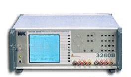


| 品牌 | WK | 型號 | 3260B(20Hz-3MHz) |
| 規格 | Precision Magnetics Analyzer | 外形尺寸 | 150*440*520(mm) |
| 重量 | 11(Kg) | 產品用途 | 精密磁性元件分析儀 |
Precision Magnetics Analyzer - 3260B
Wide frequency range of 20 Hz to 3 MHz
Fast measurement speed - up to 20
measurements per second
0.1% basic accuracy
Up to 125 A of DC bias current
Telecom measurement functions
Analysis mode with graphical displays
Comprehensive measurement functions
including leakage tests
Straightforward intuitive operation
Print test results
GPIB control with LabVIEW™ driver
Completely characterize components
graphically
At the design stage of component development it is vitally
important to understand how the component performs under
different operating conditions. This might include operation at
diverse frequencies, AC drive levels or DC bias currents.
The 3260B Precision Magnetics Analyzer can plot any of themeasurement functions, such as inductance (L) or impedance(Z), (including secondary term) against frequency, AC drivelevel or DC bias current.Frequency sweeps within the range 20 Hz to 3 MHz can beselected. There is a choice of either linear or logarithmicfrequency displays.
3260B is especially suitable for measuring parameters ontelecom transformers.
The selected parameter and its secondary value arepresented graphically. AC drive levels can be set between 1 mV and 10 V. DC bias current can be set from1 mA to 1 A internally. Using external 3265B 25 A DCBias Units bias currents can be set to a maximum of 125A.
Measure Insertion Loss and Return Loss on
telecom transformers
With the dramatic growth of PCs connected to the telephone system for Internet access has come the requirement to measure Insertion Loss (IL) and Return Loss (RL) of line matching transformers. The 3260B Precision Magnetics Analyzer not only measures IL and RL but the instrument also allows the user to enter the values for terminating resistance or impedance, if complex, and to select a damped network or blocking capacitor if required.
Specification summary
Measurement functions Z, Ø, L, C, Rac, Rdc, Q, D
Turns ratio
Primary and secondary
leakage inductance
Interwinding capacitance
Resonant frequency
Frequency range 20 Hz to 3 MHz
Basic accuracy 0.1%
Modes Analysis (graphing)
Telecom
Multi Frequency
Sequence
DC bias current 1 mA to 1 A (internal)
To 125 A (using five 3265B
DC Bias Units)
Interface GPIB
Measurement speed Up to 20 measurements/sec
Printed output of test results
Using the parallel Centronics interface the user can directly print test results including graphs for further analysis and archiving. In addition, via the GPIB interface, the instrument can be controlled from a PC and results can be read back for analysis
and storage. LabVIEW™ drivers are available on request or via our website,
Bin sort
The bin sort function allows component manufacturers to sort components in up to ten bins. Sorting is carried out either by absolute values or by percentage of values.
Component tests with up to 125 A DC bias
current
To evaluate components at high currents up to 125 A the optional 3265B DC Bias Unit is used. 25 A of DC bias current can be set in steps of 0.025 A with one unit whilst up to five units can be used in parallel to give up to 125 A DC bias current. The standard 3260B Precision Magnetics Analyzer can provide an internal DC bias from 1
mA to 1 A.
The 3265B has a number of safety and protection features including a safety interlock system to protect the user against back EMFs. It is also fully protected against over
temperature, excess voltage drop and sense lead failure.
3265B DC Bias Unit can deliver up to 25 A of DC bias current in steps of 0.025 A
SMD inductor tests up to 50 A
With the addition of the 1009 DC Bias Fixture DC bias currents up to 50 A can be applied to an SMD inductor during component test in order to evaluate the devices thoroughly at the operational bias currents.
The fixture operates with one or two 3265B Wayne Kerr DC bias units and a 3260B Precision Magnetics AnalyzerFour rear panel mounted BNC connectors and two
captive high current cables ensure simplicity and ease of use with the 3265B.
Interchangeable component test carriers ensure that the 1009 DC Bias Fixture may be used with a wide variety of devices. If a device package is not supported by one of
the standard carriers then a custom carrier design service is available. Stable component fixturing ensures high accuracy and repeatable measurements. Enclosed fixtures, with safety interlocks, minimises risk to operators
1009 DC Bias Fixture enables currents up to 50 A to be applied to an SMD inductor
Inductance plotted against frequency
Illustration of Telecomms mode
Phase plotted against frequency
Technical specifications
Precision Magnetics Analyzer - 3260B
Operation modes
Impedance mode
Inductance (L), Impedance (Z), DC Resistance (Rdc) and Capacitance (C). Series or parallel equivalent circuit Loss term: Quality factor (Q), Dissipation factor (D), AC Resistance (Rac) and Phase Angle (Ø) Analogue scale (bar graph) with nominal, absolute and percentage modes
Handler mode
Enables existing 4-wire scanners to be used
Functions as for impedance mode plus Turns Ratio
Transformer mode
Rdc of each winding, Primary or Secondary Leakage Inductance and Q, Turns Ratio, Interwinding Capacitance Insulation between windings from either winding to
screen/core is available as an option.
Telecom mode
Provides derivation of Insertion Loss (IL) and Return Loss (RL) for line matching transformers operating in the telephone speech band (100 Hz to 20 kHz). Values of line
impedance (Zo) and termination (Rt) are user selectable. Optional simulated damping network and series blocking capacitor are user configurable.
Analysis mode
Measurement parameters and test conditions set using measurement mode.
Graphical sweep versus frequency, AC drive level or DC bias current with selection of start, stop, step size, units and linear/log.
Multi-frequency mode
Measurement parameters and test conditions set using measurement mode. Up to eight frequencies with absolute or percentage limits on major term PASS/FAIL indications.
Test conditions
Low level AC drive
For measurement of L + Q, Ls + Rs, C, Z, Turns Ratio and Leakage Inductance
Frequency range
20 Hz to 3 MHz interwinding capacitance, minimum frequency 100 Hz
Steps
Increments of 1% or better across range 1800 frequencies approx. Accuracy of selected frequency ±0.01 %
Drive level
Source impedance 50 Ω
1 mV to 10 V rms into open circuit
50 μA to 200 mA rms into short circuit
Automatic Level Control (ALC) maintains level applied to
DUT at ±2%, ±1 mV of set voltage or ± 2% ±0.1 mA of setcurrent.
DC bias current
1 mA to 1 A DC is available from internal, fast settling bias supply over full frequency range Voltage compliance 20 V minimum
Safety interlock minimises operator exposure to high currents.
DC resistance
Low test level of 100 mV minimises heating of the device under test.
Short circuit current 10 mA
Insulation (option)
Test voltages of 100, 200 or 500 V DC, user selectable
Results can be displayed as a current or resistance value
Voltage accuracy ±3%
For user safety, short circuit current is limited to <2 mA
Bin Handler mode (option)
Sort to 1 of 10 bins using absolute or percentage limits.
Separate Pass/Fail output.
Up to 100 bin limit set-ups stored in non-volatile memory.
TTL interface to external bin handler via 25 way D type connector.
Telecom mode (option)
Drive level -28 to 16 dBm
Test time varies with level
Zo/Rt 50 to 2000 Ω
Test time < 1.5 s typical
Measurement speeds
For impedance, turns ratio, DC resistance and insulation 4 speeds selectable: MAXimum, FAST, MEDium and SLOW MAX (20 measurements per second)
for component sorting under GPIB remote control.
FAST Approximately 10 measurements per second.
SLOW Approximately 1 per second for increased stability and accuracy
Measurement ranges
R 0.01 mΩ to >2 GΩ* L 0.1 nH to >1000 H* C 5 fF to >1 F*
Accuracy
Inductance/Rac/Z/Cp ±0.1 %** Q ±0.1% (Q+1/Q)** D ±0.001 (1+D2)**
Turns ratio ±0.1 %** Rdc ±0.5 %
Insulation ±5 % (500 V test) Insertion loss ±0.1 dB Return loss ±1 dB
Basic accuracy varies with frequency, Zo, Rt, range and level
* Varies with measurement speed
** Varies with frequency and option chosen
General data
Input specification
Power supply 230V AC ±10% or 115V AC ±10% (selectable)
50 to 400 Hz 400 VA maximum consumption
Display
High contrast monochrome LCD 320 x 240 dot with back lighting.
Visible area 115 x 86mm. Viewing angle 45°
Measurement connections
8 front panel BNC sockets 2- or 4-wire (Kelvin) measurements with screen
at ground potential
Equivalent circuit symbols on screen.
Separate terminals for primary and secondary connections.
LEDs indicate active terminals.
Remote control (option)
Conforms with GPIB IEEE488.2 and SCPI 1992.0
Printer output
Centronics parallel printer port
Ambient conditions
Operating temperature range 0°C to 40°C.
Full accuracy 15°C to 35°C
Safety
Complies with the requirements of EN61010-1
EMC
Complies with EN50081-1, EN50082-1 generic emissions and
immunity standards by meeting with the requirements of
EN55022, IEC801.2, IEC801.3 and IEC801.4
Mechanical (approx. overall)
Height 150 mm (6“)
Width 440 mm (17 3/8“)
Depth 520 mm (20 1/2“)
Weight 11 kg (24 lb 4oz.)
Order codes and options
Description Order code
3260B Precision Magnetics Analyzer1J3260B
Supplied with user manual, power cable,
spare fuses, two transfer standard capacitors
and safety interlock jack
Options
/N Insulation resistance test (500 V)
/G Analysis function (graphs)
/T LF Telecom function
/D Bin handler
Auxiliary unit
25A DC bias unit 3265B (1 MHz)1J3265B
Supplied with user manual, power cable,
spare fuses, 4 x BNC to BNC links, daisy chain
link, rack mounting ears (unit needs rear support)
and bus bars.
25A DC bias unit 3265BQ (3 MHz)1J3265BQ
Supplied with user manual, power cable,
spare fuses, 4 x BNC to BNC links, daisy chain
link, rack mounting ears (unit needs rear support)
and bus bars.
Accessories
Description Order code
1009 DC Bias Fixture1J1009
Rack mounting kit. 3U x full width1EXA20230
Kelvin clips (fine jaws).1EVA40100
(2 sets recommended for transformer tests)
Kelvin clips (large jaws)1EVA40180
BNC to 4-terminal component fixture.1EV1006
Recommended above 500 kHz
4-terminal lead set1EV1505
(SMD Tweezers1EVA40120

批發市場僅提供代購諮詢服務,商品內容為廠商自行維護,若有發現不實、不合適或不正確內容,再請告知我們,查實即會請廠商修改或立即下架,謝謝。