


全球獨傢提供漢語,英語,法語,西班牙語,葡萄牙,德語,日語,韓語,阿拉伯語,越南語等十幾種說明書及各種語言文字說明的操作視訊,打造全球頂尖遠程探測器的領航者---深圳市歐克迪電子有限公司
中文版:
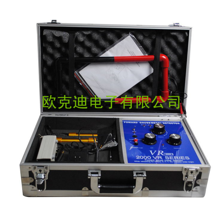
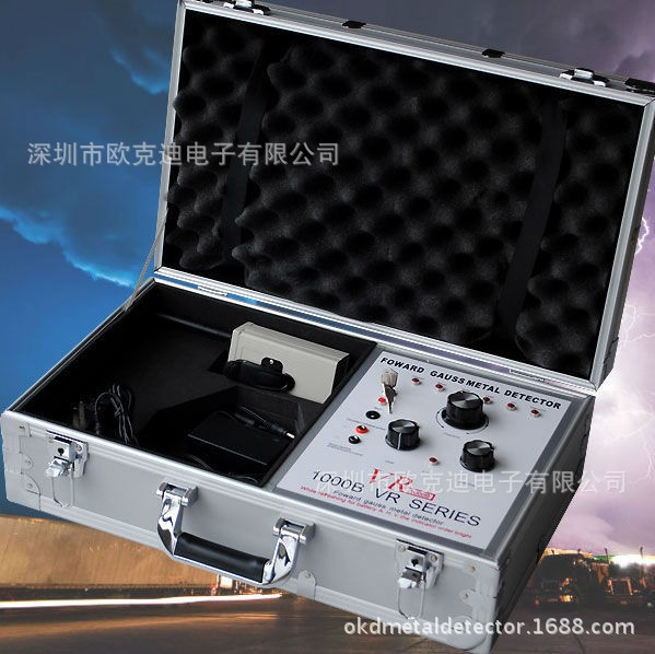
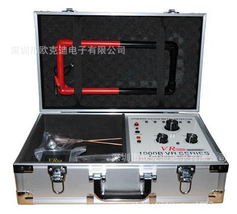
20米全球供應遠程搜索探測美國VR1000B地下鉆石金銀金屬探測器
致尊敬的使用者:
非常感謝您購買VR系列遠程定位系統,我們這套探測系統是能夠發射和接受遠至1KM以內的信號,是微電腦控製遠距離定位的探測機器。
我們這套系統研發多年,性能穩定,使用方便,現如下有幾條建議,供使用者參考,有利於很好的使用VR系列產品。
將整個系統的所有配件都放入便攜箱內,放在乾燥涼爽的地方儲存。
如果您打算超過一個月不使用它的話,請將電池取出。
使用過程中請關掉手機、呼機或其他的電力設備。
請勿將整套系統在炎熱的天氣下放如汽車內過長時間。
不要將整套機器長時間放在太陽下爆曬。
遠離火焰。
勿讓機器淋雨。
保持機器的清潔。
不要劇烈震動或搖晃機器。
經常檢查和更換電池。
堿性電池是最好的選擇。
如果測試環境是巖石或土壤比較硬的地方,建議用硬的東西挖一個洞將發射機天線埋下。
整套系統除瞭電池之外沒有消耗品,從箱中移出發射機將不予保修!!
如果您對接下來的說明有任何疑問,隨時可以打我公司電話來咨詢,技術部會盡全力給您最大的幫助。
再次感謝您對我公司的信任並購買我公司的產品!衷心祝願您早日獲得成功。
VR1000B代表瞭超深度金屬探測器的最高水平,專業人士的首選
— 深度及范圍探測模式,對六種不同金屬提供超強的探測深度及探測范圍
目標信號的追蹤方法,可根據不同的方法,追蹤目標信號,對目標物進行準確的識別探測追蹤功能,可適應不同地麵環境的變化,保持最佳的探測效果
工作模式切換功能,可分別選擇銅、銀、金、鉛、錫、寶石六種探測工作模式
應用:搜索礦脈、野外探礦、考古研究、找尋寶藏
技術參數
頻率范圍超音波:400-3000 Mhz +/- 150 Khz
最大限度持續功率:850 mA
頻率范圍:433 MHZ +/- 150 KHZ
內存儲器:EEPROM 16k x 8 Bit
電壓供給:9 - 12 V DC
存儲溫度:-40 C to +85 C
工作濕度:0-95% 無冷凝
充電電池:可持續使用24小時
重 量:約14 LBS
深 度:20米
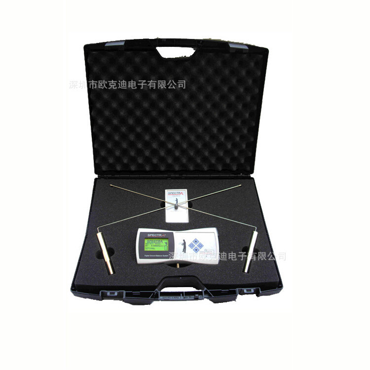
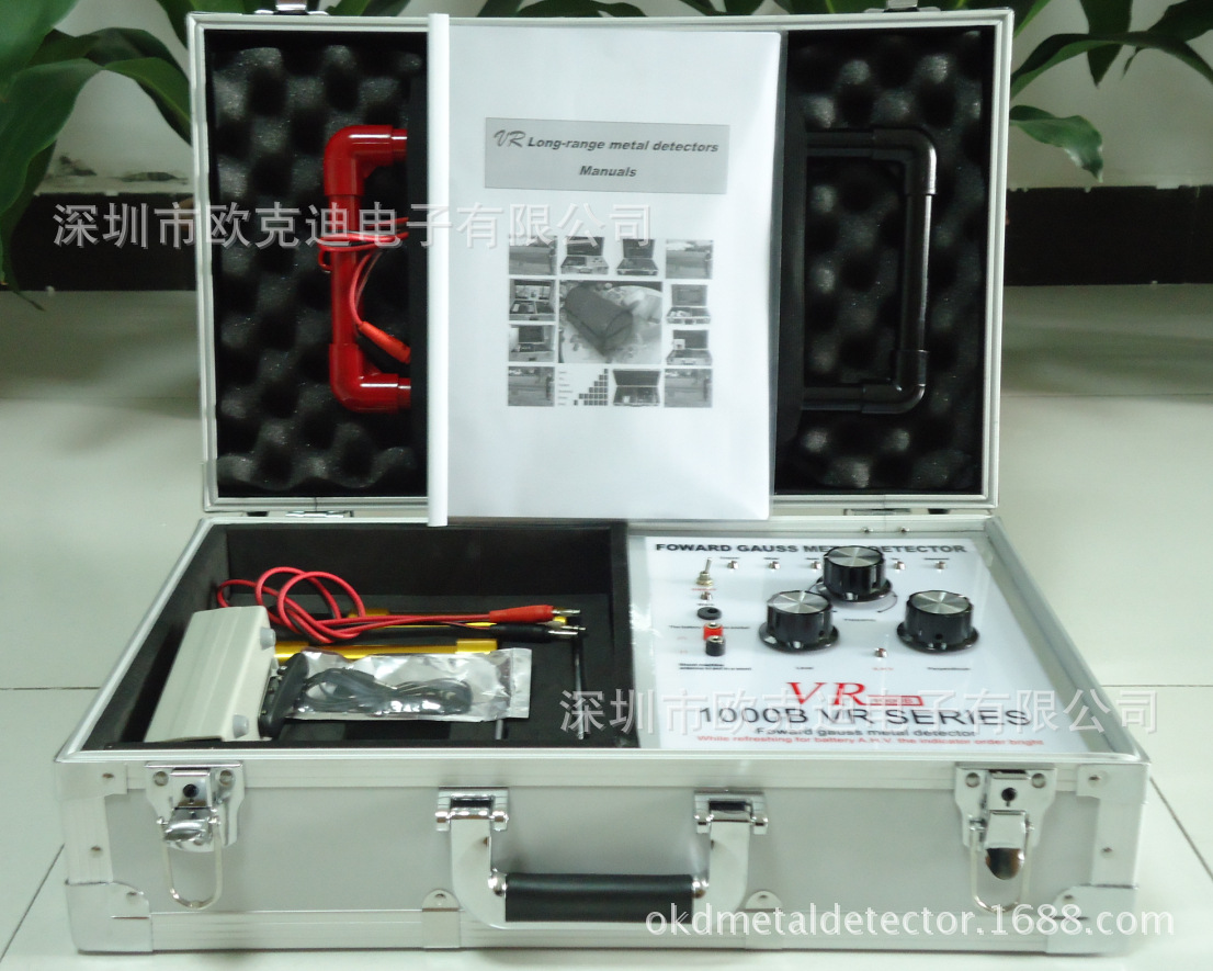
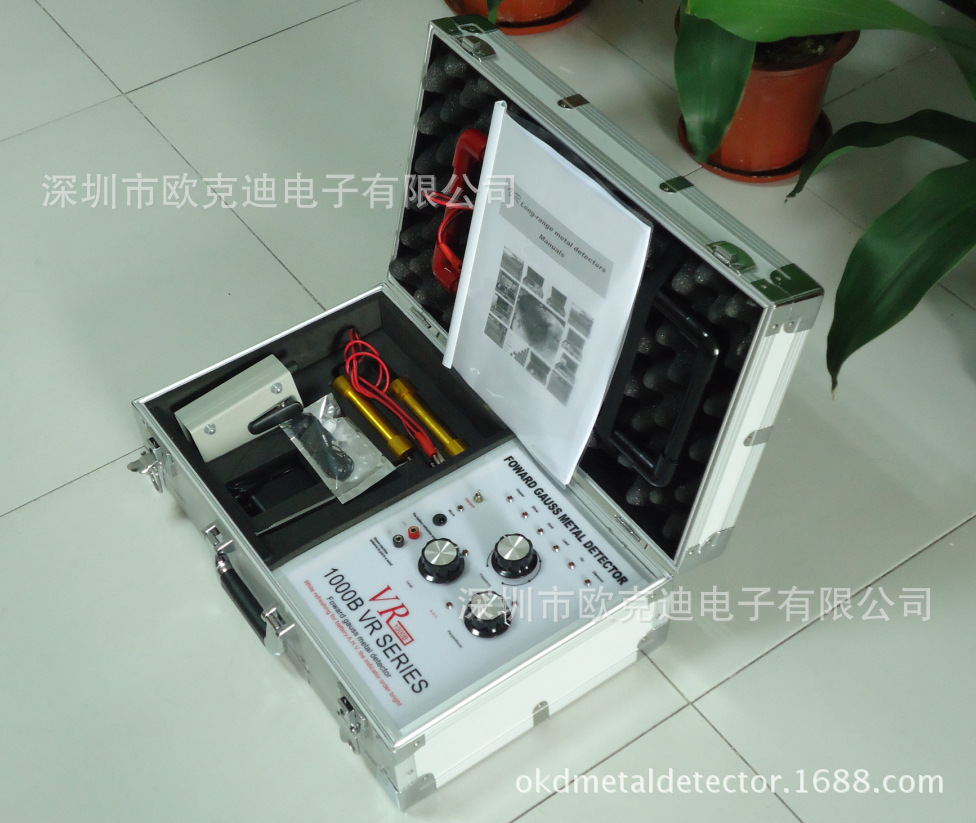
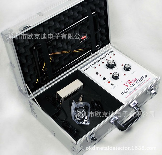
裝箱清單
打開箱子,仔細清點下例物品:
●機器主機一臺,供電電源工廠已裝好
●埋地天線一個
●接收L型天線一對
●接收器一個
●耳機一個
●充電器一個
●使用說明書一份
附加說明
●使用接收機之前把發射機電源開關至少開10分鐘左右.
●每次指示竿交叉以後,一定要把它們觸一下地麵放出其中的電荷.
●第二次使用接收機時打開發射機開關至少5分鐘以後.
●鎖定時間因操作人員而定,因此,在已知對象上做實驗來測定個人的鎖定時間是非常重要的.
●把指示竿分開20英寸並稍微向下傾,以避免讀取錯誤或不自覺的認為影響.
●最好在清晨或傍晚探測,避免風雨等惡劣氣候.
●當感覺到指示竿開始交叉時不要停下來,要讓兩竿完全交叉以後在進行其他操作.
結論:這款定位器的設計是用來尋找地下埋藏時間很長物品的。當然也可以找沒有埋入土中的物品,但效果要差的話,如果可能的話,我們建議你把物品埋入地下很長時(1至2年)並隨著時間的推移測試效果的差別。
保修條款
※凡從我公司購買的探測器,因屬於高精密產品,不接受退換貨,但可以為客戶實行終身保修服務.
※產品在使用過程中出現損壞,公司免費維修服務隻包括維修所產生的換零件費用和手工費用,客戶需承擔維修所產生的運費(進口機器需承擔國外發貨的費用),國產機器維修一般七個工作日,進口機器維修一般三十個工作日.
※在發貨的過程中產生損壞,公司負責免費調換機器,客戶不需承擔費用.
※我公司對有缺陷的零部件及其製造缺陷負責.如果發現有缺陷的零部件,我們有責任修理和更換該零件.這樣的服務是客戶享有的權利,我公司將承擔人工費和材料費.從客戶到授權服務中心的運費和材料費由客戶負責.
※我公司對由於以下原因而引起的產品損壞不負任何責任.包括事故,錯誤使用,丟失,浸水,火災或者使用環境超出瞭本產品的技術規范,在惡劣的天氣下使用,不正確的存儲,過多的雜物及沙子接觸,由於用戶試圖修理該產品或者更換零部件等非正常操作對該機器的破壞.私自打開該機器也會使保修無效.
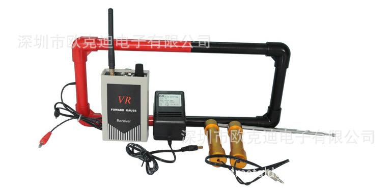
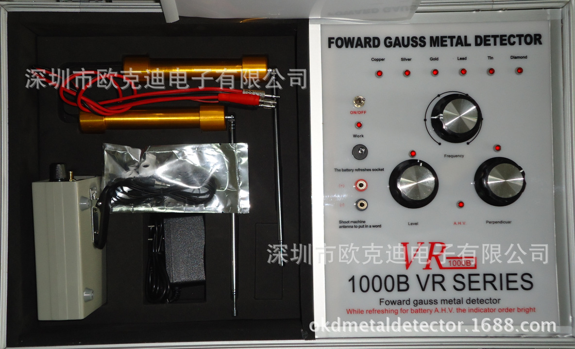
一個帶有鎖的專用箱子,裡麵裝有發射器及其他部件。該發射器是固定安裝在箱子中的,發射器的麵板上有四個LED指示燈,每個指示燈都代表著某項功能。在指示燈的下麵有頻率選擇開關,由用戶根據需要設置。在頻率選擇開關的下麵有兩個分別標有﹤水平﹥﹤垂直﹥的旋鈕。下麵有電源開關,充電插孔(機器采用優化充電電路)及超載保護裝置。
●標有水平垂直的旋鈕及對應的指示燈,它們用於調整發射波形,使機器適應地麵狀況,一般狀態下逆時針旋到最大處時對應的指示燈亮即可。在大型低阻礦藏及鹽堿地等惡劣地質狀態下要使用指示燈變暗或不亮。
●最下麵的兩個插孔是發射機天線插孔,請註意正負極的對應關系。
●在使用前要提前充電6小時,在使用時如果工作指示燈開始變暗表明電量不足,這時要給電池充電。
●接受機頂部有一個開關調諧旋鈕,用於感應量微調。
●接收機有一個工作指示燈,電池裝卸口,指示天線插孔和耳機插孔。
●接收天線是兩個密封的圓柱體,從每一個圓柱體的底座引出一條線,合並後終端和插件相接(該插頭和接收器上的電容相匹配)。每個天線可以自由伸縮。
●發射天線是一個紅色的矩形框,在矩形框的上部引出兩根線,在使用時把插頭插入發射機的天線插孔(註意正負極的對應)。將天線的底部二十厘米埋於地下。
2.開機測試
首先把發射天線連接到發射器對應的插孔內。把發射機上的開關打開到ON位置來測試指示燈。也可以同時在發射天線的旁邊放一個小型晶體管收音機,把頻率調到中波段530HZ來測試機器,打開收音機,如果發射機正常工作,則收音機將受到乾擾,然後旋轉發射器麵板上的頻率旋鈕將會使頻率指示燈依次變亮,當不同的指示燈點亮的時候,收音機乾擾音調會有變化。
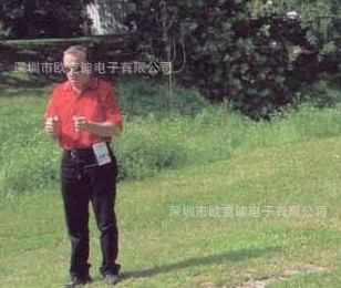
3.打開接收天線包裝後,把它連接到接受器之前要有個感性認識。需要練習如何使用它。
●把接收天線抽出15厘米左右
●每隻手拿住一個天線
●使兩手的距離保持在20厘米左右
●天線頭距離保持在15厘米左右,然後慢慢向下傾斜5厘米
●放松
●以正常的步速走動
●不要提高或晃動
●拿住天線進行練習,直到在走動時保持天線平衡,要掌握使用天線需要一些練習,但它是能有效的使用此探測器的技巧之一。
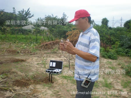
4.在你正確掌握瞭使用天線的技巧之後,可以把接收器固定在你身體的正前方,它是接收器放置的最佳位置。
●把接收器和天線連接在一起
●像第三步那樣,測試接受天線,這次要確保沒有乾擾。
5.這些部件都能正常工作後,現在可以進行區域測試瞭。測試區域的金屬碎片越少越好。
6.區域測試時,把發射器放在地麵上,把發射器的天線連接到發射器的對應插孔內。在發射器打開的時候,絕對不要插拔天線,如果那樣做,極易對機器造成傷害。在發射器的前麵,挖一個小溝,把發射天線埋到溝裡,沒到黑線處。頻率選擇設置到需要位置。打開發射器,然後順時針旋轉“水平”和“垂直”兩個旋鈕到最大處,直到它們上麵的兩個指示燈變亮(這個過程用來設置使用發射器適應地麵情況)。在5分鐘之後,站到離發射器5到8米遠處,像上麵練習使用接收天線的時候一樣,圍繞發射天線做圓周運動,保持距發射天線的距離8到12米遠,如果探測區域沒有要找的目標物,接受天線不會交叉。
7.用測試物練習使用這臺機器,學習時應盡量用稍大一些的測試物。掌握技巧後用重量大約和幾個硬幣或耳墜相當的測試物,埋在距發射器8到12米處遠。
8.重復第六步。當你正處在發射天線和測試物這條線上的時候,接收天線應該是交叉的(記住:這時測試物和發射天線之間的信號線將會形成)。當你走過這條線的時候,接收天線不會交叉。在天線交叉處做下標記。然後,再遠離發射器一些距離(如果一開始距離發射器5到8米則應到12米之處)。
重復上述過程,在接收天線交叉處做下標記。然後通過發射器和做標記的兩個地方畫一條線,這就是你確定的X軸。關掉髮射器和接受器,然後等15分鐘,把發射天線和發射器挪到一個新的地方,重復這一過程。記住要把發射天線埋進去。這次你確定瞭Y軸。X軸和Y軸的交叉處即目標物所在地。
9.第4步到第8步掌握之後,現在可以探測目標物瞭。
選擇一個實驗地,要盡量遠離城區,避免附近有高壓線,鐵路線,信號塔等。
10.確定搜索區域。
●建議您最好先埋一個測試物來測試系統和環境,重復做第6到第8步。
●在成功完成第8步之後,取走測試物,關掉髮射器。
●在開始真正的搜索之前要等15分鐘,這樣做的目的是使地下磁場信號減弱。
●當搜索想要的目標時,重復第6到第8步。
●不要在開機的狀態下移動測試,這樣會使地下電磁場紊亂。如果在使用此機器的過程中遇到問題時,你可以進行一系列簡單測試來找出原因。
●要確定電池已充電,充電器能否正常工作,如果充電器能正常工作,插上電源充電指示燈應當變亮。
●當機器打開時,檢查確認頻率選擇指示燈是否正常顯示。當旋鈕頻率選擇到固定位置時,對應的指示燈應變亮。
●AVH指示燈是不是特別明亮,它不應該是暗的。
●現在接上天線,系統誤開的時候絕對不要插入天線。
●打開發射器,用一個中波段收音機調頻到530HZ,把它放到發射天線旁邊,你隻能聽到一種連續的音調,直到不同的頻率被選擇。旋轉頻率開關,在不同的頻率被選擇的時候,你應當聽到不同的音調。
●使用這個機器確實需要一些練習,希望以上測試對你會有所幫助。
【註意事項】
★每個測試區至少要測試兩次,第二次測試的時候發射器的位置距離第一次測試的位置至少要有8米遠的距離,這樣可以避免漏掉幾米內的目標物。
★記住你的身上不應高帶有任何電子設備或金屬物體(特別是手機和呼叫機)。
★位線的初始點應是埋在地裡的發射天線。
★改變設置或改變發射器的位置時要關掉髮射器,在打開之前至少要等15分鐘(這樣做的目的是在確定交叉線之前使一個信號線電磁場變弱)。
★發射器打開時不要在測試區域內,例如任何金屬或其他測試物體。
★某種情況下,在發射天器和目標物之間形成的信號線可能會起到天線的作用,應該改變探測地點方位,多點測量。
【探測器的維護】
清洗:探盤部分是最容易臟的,可以用一塊毛巾沾上清水小心的擦洗,但是,在這裡特別說明,探頭所聯的插頭絕對不能受潮。插頭受潮後,探測器就對任何金屬都沒有反應,遇到這種情況,可以把插頭烘乾然後才使用。機器盒是不防水的。不能水洗,隻能用毛巾揩凈。下雨天不能在室外操作。
溫度:保護機器不受嚴寒,過度的冷凍會損壞機子。也不要讓它在陽光下暴曬。
鹽水:鹽水有極大的腐蝕性,如果機器碰上鹽水,應立即用清水徹底清洗,小心別讓水進入機盒,並迅速用毛巾揩乾。
售後服務:
VR系列機器常見問題:
問:為什麼實驗的時候走到信號線上天線不交叉?
答:把被測金屬和發射天線埋下後要等待最少15分鐘以上。這個時間是為瞭讓發射天線的信號放射到足夠的麵積,並與被探金屬反射形成一條信號線。
問:為什麼等瞭15分鐘瞭天線還是不交叉?
答:查看接收器的旋鈕在什麼位置。這個旋鈕是調節接收信號線強度的,順時針旋轉會增加信號線的強度,逆時針旋轉則減小信號線強度。當強度越大時越容易接收到信號線,但相應產生的誤差也就越大。練習的時候如果難以搜尋到信號線時請適當的增加信號線的強度便於探測,等操作熟練以後再逐漸的縮小信號線強度減小誤差從而更加精確的進行定位。
問:為什麼練習的時候天線會亂交叉?
答:首先有一種可能就是當地的金屬雜物比較多。比如高壓線,建築物,金屬垃圾過多等等都有可能形成假信號。此外機器不適合在城市間進行探測,所以探測的時候請盡量遠離建築物和高壓線,選擇空曠的地方。其實就是風比較大的時候也會影響探測效果,因為天線移動比較靈敏,所以有時候可能風刮也會引起天線交叉。最重要的就是要進行天線的練習,機器雖然操作簡單易懂,但是要熟練掌握卻需要花費一定的時間。
問:為什麼明明埋瞭金屬天線卻不交叉或亂交叉?
答:機器的操作需要一個理性的認知,特別是天線的操作更需要練習。建議先進行天線的練習,練習天線的時候把天線拉長10公分左右,頂端保持大概10公分的距離,兩手間保持大概30公分的距離,然後頂端稍微向下傾斜。握天線的時候手一定要放松,不要用力,手臂的肌肉也要放松。就這樣反復的練習,等熟練掌握後再進行實地的練習。
問:為什麼取走探測物後天線還會在原來的那條線上交叉?
答:就跟信號線形成需要一定的時間一樣,信號線的消失也需要等待一段時間。拿走物體後,之前形成的信號線並不是立。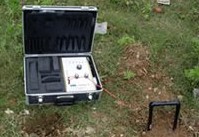


English
VR1000B
VR SERIES
LONG RANGE UNDERGROUND metaL DETECTOR
Newest upgraded deep long range metal detector.English operation panel.
The detecttarget:Gold, Diamond, tin, Lead, copper, silver.

History of VR Series
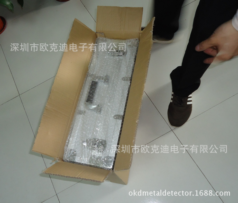
The VR™ 1000 FORWARD GAUSS™ is an advanced system utilizing advanced FORWARD GAUSS™ technology and is both an audio and visual detector. This detector was first used in the field in 1984 and the FORWARD GAUSS™ technology that it uses has proven to be (by far) the most successful developed by Vernell™ Electronics. This system was originally developed for professional archeologists and treasure hunters and has been used both on land and under water . With the original $20,000 it was out of the reach of all but the most serious. With the development of faster and more complex processing units and a reduction in the cost of materials we were able to begin offering this breakthrough technology to the general public. Part of the success of this system is that it does not look like a standard ‘metal detector’. Instead, it has the appearance of a fine, well manufactured piece of scientific equipment that one might expect to find at an archeological site. The VR™ 1000 FORWARD GAUSS™ is ‘custom built’ in a sturdy, hard side, padded case with two locks. The transmitter is case mounted and includes the Vernell ‘Standard Six’™ elements with selecor switch. The system includes an installed, rechargeable gel cell battery with charger, transmitting antenna, receiving rods and receiver with belt clip, headphones and user manual all inserted into the specially fitted case.

Place of Origin:Guangdong China (Mainland) | Brand Name: FORWARD GAUSS | Model Number:VR1000B |
Weight:7.5 KG | Size:42*28*18cm | Warranty:1 year |
Delivery Time:3-5 days | Battery Life:48h | Depth:15-30m |
Range:1000m | Payment:T/T, Cash, Moneygram Western unio | Power:850mA |
Main features:
1. Select depth and range by users, very convenient to adjust depth according to pratical situations.
2. Accurately pinpointing gold, diamond deposit, even for a samll size nugget.
3. Professional treasure hunter, high performance in anti-interference.
4. Only for gold (if you set the machine for gold), just move switch to Gold, then you can start your detection.
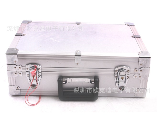
5. Two locks, prevent from being damaged and stolen.
6. Easy operation, English operation panel and manual.
7. Easy to carry, put all parts into an Aluminum box. Unit weight: 8kg including monitor and accessories.
8. Rechargeable battery, charge the machine 12h at the first time, please.
This metal detector was first used in the field in 1984 and the FORWARD GAUSS technology that it uses has proven to be (by far) the most successful.
VR system was originally developed for professional archeologists and treasure hunters and has been used both on land and under water. With the development of faster and more complex processing units and a reduction in the cost of materials, we were able to begin offering this breakthrough technology to the general public at a much more affordable cost.
Function:
(1) We add a function of indicator lights. These indicator lights show 20 different distances between the user with a receiver and the transmitter.
(2) Most common frequencies areGold, Diamond, tin, Lead, Aluminum, silver.
(3) Detecting Range: 100-1000m
(4) Detecting Depth: 15-30m
(5) After tracking target, you will have some idea of the identification and the exact pinpoint.
(6) The face (front) of the transmitter has six LEDs (channel indicator lights) across the top; each is labeled for a particular element. 
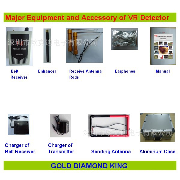
Components:
(1) A black case with aluminum trim, a handle and two locks
(2) External Battery Port
(3) The Belt Receiver
(4) Receiving Rods
(5) Battery Charger
(6) Antenna
(7) Marker Flags
(8) Operators Manual
Specification:
(1) Max Detection: 15-30m
(2) Detect Range: 100-1000m
(3) Rechargeable Battery: Continuous working 48 hours
(4) Power: 850mA
(5) Frequency: 433Mhz+/-150Khz
(6) Inner Storage: EEPROM 16k*8Bit
(7) Voltage: 9~12VDC
(8) Temperature Range: -40~85
(9) Operating Humidity: 0~95% (non-condensing)
(10) Ultrasonic Frequency: 400-3000Mhz+/-150Khz
(11) Weight: 14LBS
Package:
(1) Size/Unit: 45*32*20cm
(2) Weight/Unit: 6kg
(3) Qty./CTN: 1unit
(4) Size/CTN: 46*34*24
(5) G.W./CTN: 7.5kg
INSTRUCTIONS
- 1. Carefully unpack and familiarize yourself with the components of your VR Series Remote Sensing Detector System. The components are:
- The Transmitter - the transmitter is a gray box measuring approximately 8” x 6.5” x 3” with two dials, one toggle switch, up to six lights and two plug receptacles on the front (one red and one black). There is a sliding door on the back covering the receptacle for the batteries. This component uses four ‘AA’ or ‘C’ cell batteries as supplied.
- The Ground Probes (2) - these are white capsule shaped devices having sharpened brass rods protruding from the bottom and wires protruding from the top. One wire terminates in a red plug and the other terminates in a black plug (corresponding to the receptacles on the front of the transmitter).
- The Belt Receiver - this is a black box that measures approximately 2.5” x 3.5” x 1”. On the top of is a push button, one light and a plug receptacle. There is a belt clip on the back of the box and near the bottom of the back there is a sliding door in which to put the battery. This component takes one nine volt battery. The red button on top can be pushed to test the battery.
- Receiving Rods (2) - these are sealed copper cylinders. A wire protrudes from the bottom of each cylinder. These wires merge to form one wire that terminates with a plug., this plug fits the receptacle on the belt receiver. Extending perpendicularly from each cylinder is a brass rod sheathed in copper tubing. The copper tube slides forward to extend the rods. The receiver is turned on when the rods are plugged in.
2. Install batteries into transmitter unit. Set Anomaly Weight Control to 0. Move toggle switch to the ON position to test light(s). Transmitter may be tested by placing a small transistor radio, tuned to the lowest AM frequency, next to transmitter while it is on. There should be interference on the radio if the transmitter is functioning. If the unit is programmed with more than one element then a the interference will change tone when the different elements are seleced.
3. After unpacking the antenna rods, and before you plug them into the receiving module, you will need to practice with them to ‘get the feel’ of them.
- Extend the rods approximately six inches.
- Take one rod in each hand.
- Hold hands about twelve inches apart.
- Start with the ends of the rods about five inches apart and tilted slightly downward about two inches.
- RELAX
- Walk at a normal pace.
- Do not raise or swing rods.
As you walk watch the rods. When you walk over a metal object the ends should cross. If rods do not respond to metal objects, try changing the position of your hands until the rods cross every time you cross over a metal object.
Mastering the use of the rods may take some practice, but is one of the key skills needed to effectively use your system.
4. After you have mastered using the rods, attach the receiver unit to your belt in the center front of your body. This is the optimum location for the receiver.
- Plug the antenna rods into the receiver unit.
- Test the rods as you did in step three. This is to make sure that there is no interference.
5. Now that the components have been tested and found functioning it is time to field test the system. Field test system in an area as free of metal debris as possible.
6. To field test the system, place transmitter on the ground, plug the ground probes into corresponding receptacles on the front of the transmitter. Set the selector to the desired element. Turn on transmitter. Be sure that Anomaly Weight Control is set to 0. After three to five minutes attach belt receiver to belt at the front of the body. Plug in receiving rods. Using the rods, as practiced, walk a 20’ to 25’ diameter circle around the transmitter. If the area is clear of metal objects, the rods should not cross.
7. To practice using the system bury a test object, approximately the weight of several coins or pieces of jewelry, about 50 feet from the transmitter.
8. Repeat Step 6. Now the rods should cross when the line between the test target and the transmitter is crossed. Continue to walk the signal line in a serpentine pattern until you come to your target. (See Diagram I) If the rods do not cross, further practice with the rods as detailed in Step 2 may be needed.
9. After Steps 4 through 8 have been mastered it is time to try to locate unknown targets.
10. selec search site. It is suggested that you bury a test target at the search site to test the system and conditions. Repeat Steps 6 through 8. After successfully completing Step 8 remove test target and turn off transmitter. Wait about fifteen minutes before beginning actual search. Repeat Steps 6 through 8 while searching for desired target element.
11. Once target has been located, turn the Anomaly Weight Control to the right one number at a time. When the rods will no longer cross the setting number is the minimum number of ounces of the element in the target. If the target exceeds the greatest number on the right move knob to 0 then one number to the left until the rods no longer cross. This number indicates the minimum number of pounds in the target.
NOTES:
1. In the event that you place the transmitter within 25 feet of the target, a line will be formed through and past the target for an unknown distance. Therefore it is always best to triangulate a target before digging. See illustration and information on triangulation in this manual.
2. Remember that you should not have any electronic devices or metal objects attached to your body, (especially cellular phones and pagers).
3. Line is developed from the probes in the ground not from the case and/or transmitter.
4. Turn off transmitter when changing elements or when changing position of transmitter for triangulation, and wait at least ten (10) minutes before turning back on. (This is to allow the first line to fade before developing the intersecting line.)
5. Do not add any metal objects to the area being tested while the transmitter is turned on.


批發市場僅提供代購諮詢服務,商品內容為廠商自行維護,若有發現不實、不合適或不正確內容,再請告知我們,查實即會請廠商修改或立即下架,謝謝。