Critical linkis anembedded systemsdeveloper with expertise in a broad range of electronics applications.Critical linkdesigns leading-edgedigital processingplatforms, includingEmbedded DSP Card EnginesandScientificandVision Cameras.Critical linkhas developed and refined a robust framework of designs, pre-engineered interface cores, protocol and device support, and software tools. Critical link, LLC MityDSP
www.Criticallink.comMityDSP-L138F Processor Card
www.MityDSP.com12-JUL-2011
1 Copyright © 2010, Critical link LLC
Specifications Subject to Change
FEATURES
· TI OMAP-L138 Dual Core Application
Processor
- 456 MHz (Max) C674x VLIW DSP
- Floating Point DSP
- 32 KB L1 Program Cache
- 32 KB L1 Data Cache
- 256 KB L2 cache
- 1024 KB boot ROM
- JTAG Emulation/Debug
- 456 MHz (Max) ARM926EJ-S MPU
- 16 KB L1 Program Cache
- 16 KB L1 Data Cache
- 8 KB Internal RAM
- 64 KB boot ROM
- JTAG Emulation/Debug
· On-Board Xilinx Spartan-6 FPGA
- XC6SLX16
- 1050 Mbps data rates
- 576 KBits Block RAM
- 2,278 Slices (6 Input LUTs)
- JTAG Interface/Debug
· 128 MB mDDR2 CPU RAM
· 256 MB Parallel NAND FLASH
· 8 MB SPI based NOR FLASH
· Integrated Power Management
· Standard SO-DIMM-200 Interface
- 96 FPGA User I/O Pins
- 10/100 EMAC MII / MDIO
- 2 UARTS
- 2 McBSPs
- 2 USB Ports
- Video Output
- Camera/Video Input
- MMC/SD
- SATA
- Single 3.3V Power Supply
(actual size)
APPLICATIONS
· Embedded Instrumentation
· Industrial Automation
· Industrial Instrumentation
· Medical Instrumentation
· Embedded Control Processing
· Network Enabled Data Acquisition
· Test and Measurement
· Software Defined Radio
· Bar Code Scanners
· Power Protection Systems
· Portable Data Terminals
BENEFITS
· Rapid Development / Deployment
· Multiple Connectivity and Interface
Options
· Rich User Interfaces
· High System Integration
· Fixed & Floating Point Operations in
Single CPU
· High Level OS Support
- Linux Kernel 2.6
- QNX 6.4
- Windows XP Embedded Ready
· Embedded Digital Signal Processing
DEscriptION
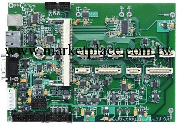
The MityDSP-L138F is a highly configurable, very small form-factor processor card that
features a Texas Instruments OMAP-L138 456 MHz (max) Applications Processor
(OMAP) tightly integrated with the Xilinx Spartan-6 XC6SLX16 Field Programmable
Gate Array (FPGA), FLASH (NAND, and NOR) and mDDR2 RAM memory
subsystems. The design of the MityDSP-L138F allows end users the capability to
Critical link, LLC MityDSP
www.Criticallink.comMityDSP-L138F Processor Card
www.MityDSP.com12-JUL-2011
2 Copyright © 2010, Critical link LLC
Specifications Subject to Change
develop programs/logic images for both the OMAP and the FGPA. The MityDSP-L138F
provides a complete and flexible digital processing infrastructure necessary for the most
demanding embedded applications development.
The onboard OMAP-L138 processor provides a dual CPU core topology. The OMAPL138
includes an ARM926EJ-S micro-processor unit (MPU) capable of running the rich
software applications programmer interfaces (APIs) expected by modern system
designers. The ARM architecture supports several operating systems, including linux
and windows XP embedded. In addition to the ARM core, the OMAP-L138 also
includes a TMS320C674x floating point digital signal processing (DSP) core. The DSP
core supports the freely provided TI DSP/BIOS real-time kernel. Users can leverage the
DSP to execute real-time compute algorithms (codecs, image/data processing,
compression techniques, filtering, etc.)
SO-DIMM-200 (DDR2 Connector)
System
Clocks
EMIFA (16-bit)
GND
3.3 V
JTAG/Emulator
EMAC MII/MDIO
UART 0,1,2
MMCSD 0
McBSP 0,1
SPI 0,1
I2C 0,1
McASP
eCAP
eHRPWM
Timers
SATA
Texas Instruments
OMAP-L138
456-MHz ARM926EJ-S ™ RISC MPU
456-MHz C674x VLIW DSP
(Many pins are multiplexed between peripherals)
JTAG
Header
8MB NOR Flash
(SPI interface)
For uBoot
bootloader
Xilinx
Spartan-6
FPGA
XC6SLX16
CSG324 pkg.
Power
Management
128MB
mDDR Memory
16-bit wide
256MB
NAND Flash
8-bit wide
For root FFS
Programmable I/O
Programmable I/O
Boot
Config
USB 0,1
Resets & RTC
1.2V
1.8V
2.5V
3.3V
JTAG
MMCSD 1
EMAC RMII
UHPI
uPP
LCD
VPIF I/O
Boot Config
I/O Bank Power
I/O Bank Power
FPGA I/O
Banks can be
1.8V, 2.5V, or
3.3V
Emulator
Header
Figure 1 MityDSP-L138F Block Diagram
Figure 1 provides a top level block diagram of the MityDSP-L138F processor card. As
shown in the figure, the primary interface to the MityDSP-L138F is through a standard
SO-DIMM-200 card edge interface. The interface provides power, synchronous serial
connectivity, and up to 96 pins of configurable FPGA I/O for application defined
interfacing. Details of the SO-DIMM-200 connector interface are included in the SODIMM-
200 Interface Description, below.
Critical link, LLC MityDSP
www.Criticallink.comMityDSP-L138F Processor Card
www.MityDSP.com12-JUL-2011
3 Copyright © 2010, Critical link LLC
Specifications Subject to Change
FPGA Bank I/O
The MityDSP-L138F provides 96 lines of FPGA I/O directly to the SO-DIMM-200 card
edge interface. The 96 lines of FPGA I/O are distributed across 2 banks of the FPGA.
These I/O lines and their associated logic are completely configurable within the FPGA
at the end user’s discretion.
With the Xilinx Spartan-6 series FPGA, each of the user controlled banks may be
configured to operate on a different electrical interface standard based on input voltage
provided at the card edge connector. The banks support 3.3V, 2.5V, and 1.8V standard
CMOS switching level technology. In addition, the I/O lines from the FPGA have been
routed as differential pairs and support higher speed LVDS standards as well as SSTL 2.5
switching standards. Various forms of termination (pull-up/pull-down, digitally
controlled impedance matching) are available within the FPGA switch fabric. Refer to
the Xilinx Spartan 6 user’s guide for more information.
OMAP-L138 mDDR2 Memory Interface
The OMAP-L138 includes a dedicated DDR2 SDRAM memory interface shared between
the onboard ARM and DSP cores. The MityDSP-L138F includes 128 MB of mDDR2
RAM integrated with the OMAP-L138 processor. The bus interface is capable of burst
transfer rates of 600 MB / second.
OMAP-L138 SPI NOR FLASH Interface
The MityDSP-L138F includes 8 MB of SPI NOR FLASH. This FLASH memory is
intended to store a factory provided bootloader, and typically a compressed image of a
linux kernel for the ARM core processor.
EMIFA - FPGA / NAND FLASH Interface
The OMAP-L138 and the Spartan-6 FPGA are connected using the DSP Asynchronous
External Memory Interface (EMIFA). The EMIFA interface includes 3 chip selec
spaces. The EMIF interface supports multiple data width transfers and bus wait state
configurations based on chip selec space. 8, and 16 bit data word sizes may be used.
Two of the three chip selec lines (CE2, CE3) are reserved for the FPGA interface. The
MityDSP-L138F also includes 4 lines between the FPGA and the OMAP for the purposes
of generating interrupt signals.
In addition to the FPGA, 256 MB of on-board NAND FLASH memory is connected to
the OMAP-L138 using the EMIFA bus. The FLASH memory is 8 bits wide and is
connected to third chip selec line of the EMIFA (CE1). The FLASH memory is
typically used to store the following types of data:
- ARM linux / windows XP / QNX embedded root file-system
- FPGA application images
- runtime DSP or ARM software
- runtime application data (non-volatile storage)
Critical link, LLC MityDSP
www.Criticallink.comMityDSP-L138F Processor Card
www.MityDSP.com12-JUL-2011
4 Copyright © 2010, Critical link LLC
Specifications Subject to Change
OMAP-L138 Camera and Video Interfaces
The OMAP-L138 includes an optional video port I/O interface commonly used to drive
LCD screens as well as a camera input interface. These interfaces have been routed to
the FPGA, which may be routed to the FPGA output pins on the SO-DIMM-200
connector. By routing the video data through the FPGA, additional user customization
and/or processing (e.g., overlays of video output, preprocessing or filtering of camera
input) may be offloaded from the OMAP-L138 to the FPGA for compute intensive
applications.
Debug Interface
Both the JTAG interface signals for the FPGA and the JTAG and emulator signals for the
OMAP-L138 processor have been brought out to solder pads supporting an onboard set
of standard JTAG connectors. Normally, the JTAG connectors are not installed. They
may be easily added for development purposes at Critical link or on site.
Software and Application Development Support
Users of the MityDSP-L138F are encouraged to develop applications and FPGA
firmware using the MityDSP-L138F hardware and software development kit provided by
Critical link LLC. The development kit includes an implementation of an
OpenEmbedded board support package providing an Angstrom based linux distribution
and compatible gcc compiler tool-chain with debugger. In addition, the development kit
includes support libraries necessary to program the DSP core using the TI Code
Composer Studio DSP compiler tool-chain.
To support rapid FPGA and applications development, netlist components - compatible
with the Xilinx ISE FPGA synthesis tool – for commonly used FPGA designs and a
corresponding set of linux loadable kernel modules and/or DSP interface APIs are
included. The libraries provide the necessary functions needed to configure the
MityDSP-L138F, program standalone embedded applications, and interface with the
various hardware components both on the processor board as well as a custom
application carrier card. The libraries include several interface “cores” – FPGA and DSP
software modules designed to interface with various high performance data converter
modules (ADCs, DACs, LCD and touchscreen interfaces, etc) – as well as bootloading
and FLASH programming utilities.
Growth Options
The OMAP-L138 has been designed to support several upgrade options. These options
include various speed grades, memory configurations, and operating temperature
specifications including commercial and industrial temperature ranges. The available
options are listed in the section below containing ordering information. For additional
ordering information and details regarding these options, or to inquire about a particular
configuration not listed below, please contact a Critical link sales representative.
Critical link, LLC MityDSP
www.Criticallink.comMityDSP-L138F Processor Card
www.MityDSP.com12-JUL-2011
5 Copyright © 2010, Critical link LLC
Specifications Subject to Change
ABSOLUTE MAXIMUM RATINGS
If Military/Aerospace specified cards are
required, please contact the Critical link
Sales Office or unit Distributors for
availability and specifications.
Maximum Supply Voltage, Vcc 3.5 V
Storage Temperature Range -65 to 80C
Shock, Z-Axis ±10 g
Shock, X/Y-Axis ±10 g
OPERATING CONDITIONS
Ambient Temperature
Range
0oC to 70oC
Humidity 0 to 95%
Noncondensing
Vibration, Z-Axis TBS
Vibration, X/Y-Axis TBS
SO-DIMM-200 Interface Description
The primary interface connector for the MityDSP-L138F is the SO-DIMM card edge
interface.
Table 1 SO-DIMM Pin-Out
Pin I/O Signal Pin I/O Signal
1 - +3.3 V in 2 - +3.3 V in
3 - +3.3 V in 4 - +3.3 V in
5 - +3.3 V in 6 - +3.3 V in
7 - GND 8 - GND
9 - GND 10 - GND
11 I RESET_IN# 12 EXT_BOOT#
13 O SATA_TX_P 14 I/O GP0_7
15 O SATA_TX_N 16 I/O GP0_10
17 I SATA_RX_P 18 I/O GP0_11
19 I SATA_RX_N 20 I/O GP0_15
21 I USB0_ID 22 I/O GP0_6
23 I/O USB1_D_N 24 I/O GP0_14
25 I/O USB1_D_P 26 I/O GP0_12
27 O USB0_VBUS 28 I/O GP0_5
29 I/O USB0_D_N 30 I/O GP0_13
31 I/O USB0_D_P 32 I/O GP0_1
33 O USB0_DRVVBUS 34 I/O GP0_4
35 - 3V RTC Battery 36 I/O GP0_3
37 - +3.3 V in 38 - +3.3 V in
39 - +3.3 V in 40 - +3.3 V in
41 - GND 42 - GND
43 I/O SPI1_MISO 44 I/O GP0_2
45 I/O SPI1_MOSI 46 I/O GP0_0
47 I/O SPI1_ENA 48 I/O GP0_8
49 I/O SPI1_CLK 50 I/O GP0_9
Critical link, LLC MityDSP
www.Criticallink.comMityDSP-L138F Processor Card
www.MityDSP.com12-JUL-2011
6 Copyright © 2010, Critical link LLC
Specifications Subject to Change
Pin I/O Signal Pin I/O Signal
51 I/O SPI1_SCS1 52 I/O MMCSD0_DAT7
53 I/O Reserved 54 I/O MMCSD0_DAT6
55 I/O I2C0_SCL 56 I/O MMCSD0_DAT5
57 I/O I2C0_SDA 58 I/O MMCSD0_DAT4
59 I/O UART2_TXD /
I2C1_SDA
60 I/O MMCSD0_DAT3
61 I/O UART2_RXD / I2C1_SCL 62 I/O MMCSD0_DAT2
63 I/O GND 64 I/O GND
65 I/O UART1_TXD 66 I/O MMCSD0_DAT1
67 I/O UART1_RXD 68 I/O MMCSD0_DAT0
69 I/O MDIO_CLK 70 I/O MMCSD0_CMD
71 I/O MDIO_DAT 72 I/O MMCSD0_CLK
73 I/O MII_RXCLK 74 I/O MII_TXCLK
75 I/O MII_RXDV 76 I/O MII_TXD3
77 I/O MII_RXD0 78 I/O MII_TXD2
79 I/O MII_DXD1 80 I/O MII_TXD1
81 I/O MII_DXD2 82 I/O MII_TXD0
83 I/O MII_DXD3 84 I/O MII_TXEX
85 - GND 86 - GND
87 I/O MII_CRS 88 I/O MII_COL
89 I/O MII_RXER 90 I/O FPGA_SUSPEND
91 I/O B1 _47_P.U17 92 I/O B1 _48_P.M14
93 I/O B1_ 47_N.U18 94 I/O B1_ 48_N.N14
95 I/O B1 _45_P.T17 96 I/O B1 _46_P.N15
97 I/O B1_ 45_N.T18 98 I/O B1_ 46_N.N16
99 I/O B1_43_P.P17 100 I/O B1 _44_P.L12
101 I/O B1_43_N.P18 102 I/O B1_ 44_N.L13
103 I/O B1_41_P.N17 104 I/O B1 _42_P.K12
105 I/O B1_41_N.N18 106 I/O B1_ 42_N.K13
107 - GND 108 - GND
109 I/O B1_39_P.M16 110 I/O B1 _40_P.L15
111 I/O B1_39_N.M18 112 I/O B1_ 40_N.L16
113 I/O B1_37_P.L17 114 I/O B1 _38_P.K15
115 I/O B1_37_N.L18 116 I/O B1_ 38_N.K16
117 I/O B1_35_P.K17 118 I/O B1 _36_P.J13
119 I/O B1_35_N.K18 120 I/O B1_ 36_N.K14
121 I/O B1_33_P.J16 122 I/O B1 _34_P.H15
123 I/O B1_33_N.J18 124 I/O B1_ 34_N.H16
125 I/O B1_31_P.H17 126 I/O B1 _32_P.H13
127 I/O B1_31_N.H18 128 I/O B1_ 32_N.H14
129 - GND 130 - GND
131 I/O B1_29_P.G16 132 I/O B1 _30_P.F15
133 I/O B1_29_N.G18 134 I/O B1_ 30_N.F16
135 I/O B1_27_P.F17 136 I/O B1 _28_P.H12
137 I/O B1_27_N.F18 138 I/O B1_ 28_N.G13
139 I/O B1_25_P.E16 140 I/O B1 _26_P.F14
141 I/O B1_25_N.E18 142 I/O B1_ 26_N.G14
143 I/O B1_23_P.D17 144 I/O B0 _24_P.F13
145 I/O B1_23_N.D18 146 I/O B0_ 24_N.E13
147 I/O B1_21_P.C17 148 I/O B0 _22_P.D14
149 I/O B1_21_N.C18 150 I/O B0_ 22_N.C14
Critical link, LLC MityDSP
www.Criticallink.comMityDSP-L138F Processor Card
www.MityDSP.com12-JUL-2011
7 Copyright © 2010, Critical link LLC
Specifications Subject to Change
Pin I/O Signal Pin I/O Signal
151 - GND 152 - GND
153 I/O B0_19_P.B16 154 I/O* B0 _20_P.F12*
155 I/O B0_19_N.A16 156 I/O* B0_ 20_N.E12*
157 I/O B0_17_P.C15 158 I/O* B0 _18_P.D12*
159 I/O B0_17_N.A15 160 I/O* B0_ 18_N.C12*
161 I/O B0_15_P.B14 162 I/O* B0 _16_P.F11*
163 I/O B0_15_N.A14 164 I/O* B0_ 16_N.E11*
165 I/O B0_13_P.C13 166 I/O B0 _14_P.D11
167 I/O B0_13_N.A13 168 I/O B0_ 14_N.C11
169 I/O B0_11_P.B12 170 I/O* B0 _12_P.E7*
171 I/O B0_11_N.A12 172 I/O* B0_ 12_N.E8*
173 - GND 174 - GND
175 I/O B0_9_P.B11 176 I/O B0 _10_P.D9
177 I/O B0_9_N.A11 178 I/O B0_ 10_N.C9
179 I/O B0_7_P.C10 180 I/O B0 _8_P.D8
181 I/O B0_7_N.A10 182 I/O B0_ 8_N.C8
183 I/O B0_5_P.B9 184 I/O B0 _6_P.D6
185 I/O B0_5_N.A9 186 I/O B0_ 6_N.C6
187 I/O B0_3_P.B8 188 I/O B0 _4_P.B6
189 I/O B0_3_N.A8 190 I/O B0_ 4_N.A6
191 I/O B0_1_P.C7 192 I/O B0 _2_P.C5
193 I/O B0_1_N.A7 194 I/O B0_ 2_N.A5
195 - GND 196 - GND
197 - VCCO_1 198 - VCCO_0
199 - VCCO_1 200 - VCCO_0
* The Xilinx 6SLX45 FPGA does not bond I/O Buffers to balls E7, E8, F11,
E11, D12, C12, E12, and F12 of the package used for this module. For
MityDSP-L138F configurations using this FPGA option, these edge connector
signals should be treated as no-connects and will not function as FPGA I/O
lines.
The signal group description for the above pins is included in Table 2
Table 2 Signal Group Description
Signal / Group I/O Description
3.3 V in N/A 3.3 volt input power referenced to GND.
EXT_BOOT# I Bootstrap configuration pin. Pull low to configure
booting from external UART1.
RESET_IN# I Manual Reset. When pulled to GND for a
minimum of 1 usec, resets the DSP processor.
SPI_XXXX I/O The pins with an SPI_ prefix are direct
connections to the OMAP-L138 pins supporting
the SPI1 interface. The SPI1_CLK, SPI1_ENA,
SPI1_MISO, SPI1_MOSI pins must remain
configured for the SPI function in order to support
interfacing to the on-board SPI boot ROM. For
Critical link, LLC MityDSP
www.Criticallink.comMityDSP-L138F Processor Card
www.MityDSP.com12-JUL-2011
8 Copyright © 2010, Critical link LLC
Specifications Subject to Change
Signal / Group I/O Description
details please refer to the OMAP-L138 processor
specifications.
MII_XXXX I/O The pins with an MII_ prefix are direct
connections to the OMAP-L138 pins supporting
the media independent interface (MII) function.
The MII pins provide multiplex capability and
may alternately be used as UART, GPIO, and SPI
control pins. For details please refer to the
OMAP-L137 processor specification.
MDIO_XX I/O The MDIO_CLK and MDIO_DAT signals are
direct connects to the corresponding MDIO
signals on the OMAP-L138 processor. These pins
may be configured for GPIO.
GP0_X IO General Purpose / multiplexed pins. These pins are
direct connects to the corresponding GP0[X] pins
on the OMAP-L138 processor. The include
support for the McASP, general purpose I/O,
UART flow control, and McBSP 1. For details
please refer to the OMAP-L138 processor
specifications.
SATA_TX_P/N O These pins are direct connects to the OMAP-L138
SATA_TX differential Serial ATA controller pins.
SATA_RX P/N I These pins are direct connects to the OMAP-L138
SATA_TX differential Serial ATA controller pins.
GND N/A System Digital Ground.
BX_Y_P.ZZ,
BX_Y_N.ZZ
IO FPGA I/O pins. These pins are routed directly to
FPGA pins ZZ. The “X” indicates which FPGA
bank the pin is allocated. The bank is either 0 or
1. The FPGA fabric supports routing pins in
differential pairs, the Y_P and Y_N portion of the
name indicates the pair number and polarity. The
pins have been routed in pairs with phase matched
line lengths.
VCCO_X I FPGA Bank interface power input. These pins
must be tied to the desired voltage used for the
FPGA Bank 0 or 1 interface pins. Please refer to
the VCCO input pin specifications for the Xilinx
Spartan 6 family of devices for further
information. Typical values are 3.3V and 2.5
volts.
USB0_XXXX,
USB1_XXXX
I/O The USBN_ prefixed pins are direct connects to
the corresponding pins on the OMAP-L138
processor. For details please refer to the OMAPL138
processor specifications.
Critical link, LLC MityDSP
www.Criticallink.comMityDSP-L138F Processor Card
www.MityDSP.com12-JUL-2011
9 Copyright © 2010, Critical link LLC
Specifications Subject to Change
OMAP-L138 JTAG Interface Description (J2)
Table 3 OMAP-L138 JTAG Connector Pad
Pin I/O Signal Pin I/O Signal
1 I TMS 2 I TRST
3 I TDI 4 - GND
5 - 3.3V 6 - KEY
7 O TDO 8 - GND
9 O RTCK 10 - GND
11 I TCK 12 - GND
13 O EMU0 14 O EMU1
FPGA JTAG Interface Description (J3)
Table 4 FPGA JTAG Connector Pad
Pin I/O Signal Pin I/O Signal
1 - GND 2 O VCCAUX
3 - GND 4 I TMS
5 - GND 6 I TCK
7 - GND 8 O TDO
9 - GND 10 I TDI
11 - GND 12 - No Connect
13 - GND 14 - No Connect
Critical link, LLC MityDSP
www.Criticallink.comMityDSP-L138F Processor Card
www.MityDSP.com12-JUL-2011
10 Copyright © 2010, Critical link LLC
Specifications Subject to Change
ELECTRICAL CHARACTERISTICS
Table 5: Electrical Characteristics
Symbol Parameter Conditions Min Typ Max Units
V33 Voltage supply, 3.3 volt input. 3.2 3.3 3.4 Volts
I33 Quiescent Current draw, 3.3 volt input TBS TBS mA
I33-max Max current draw, positive 3.3 volt input. TBS TBS mA
FCPU CPU internal clock Frequency (PLL output) 25 300 456 MHz
FEMIF EMIF bus frequency Must be ½ CPU - 100 - MHz
1. Power utilization of the MityDSP-L138F is heavily dependent on end-user application. Major
factors include: ARM CPU PLL configuration, DSP Utilization FPGA utilization, and external
DDR2 RAM utilization.
ORDERING INFORMATION
The following table lists the orderable module configurations. For shipping status,
availability, and lead time of these or other configurations please contact your Critical
link representative.
Table 6: Orderable Model Numbers
Model
ARM and
DSP Speed
FPGA
NOR
Flash
NAND Flash RAM
Operating
Temp
L138-DG-225-RI 375 MHz 6SLX16 8MB 256MB 128MB -40oC to 85o C
L138-DI-236-RC 375 MHz 6SLX45 8MB 512MB 256MB 0oC to 70o C
L138-DI-236-RI 375 MHz 6SLX45 8MB 512MB 256MB -40oC to 85o C
L138-FG-225-RC 456 MHz 6SLX16 8MB 256MB 128MB 0oC to 70o C
L138-FI-236-RC 456 MHz 6SLX45 8MB 512MB 256MB 0oC to 70o C
Critical link, LLC MityDSP
www.Criticallink.comMityDSP-L138F Processor Card
www.MityDSP.com12-JUL-2011
11 Copyright © 2010, Critical link LLC
Specifications Subject to Change
MECHANICAL INTERFACE
A mechanical outline of the MityDSP-L138F is illustrated in Figure 2, below.
Figure 2 MityDSP-L138F Mechanical Outline
Critical link, LLC MityDSP
www.Criticallink.comMityDSP-L138F Processor Card
www.MityDSP.com12-JUL-2011
12 Copyright © 2010, Critical link LLC
Specifications Subject to Change
REVISION HISTORY
Date Change Description
7-NOV-2009 Preliminary Draft, product overview
10-NOV-2009 Updates after initial review.
15-JAN-2010 Updates to features, applications and benefits
16-MAR-2010 Finalize connector pin-outs. updat mechanical outlines.
6-APR-2010 updat product photo and speed grade.
21-APR-2010 updat specifications and options.
26-JUL2010 updat ordering information, images and mechanical
drawing.
11-FEB-2011 Correct edge connector Table 1. updat speed grade to
max 456 MHz. Updated DDR rate to support 150 MHz
clocking. updat model p/n table.
02-JUN-2011 updat edge connector Table 1 to indicate unavailable
FPGA pins for 6SLX45 options.
12-JUL-2011 updat NAND to indicate 8 bit data width. updat block
diagram accordingly. Critical link, LLC MityDSP
www.criticallink.comMityDSP Processor Card
28-AUG-2007
1 Copyright © 2007, Critical link LLC
FEATURES
· TI TMS320C6711 Digital Signal
Processor
- 200 MHz
- Hardware Floating Point Unit
- 64 KB L2 cache
- 2 Integrated McBSPs
- JTAG Emulation/Debug
· On-Board Xilinx FPGA
- XC3S400
- 300 MHz Clock Logic
- 288 KBits Block RAM
- 3,584 Slices
- JTAG Interface/Debug
· 8 MB CPU SDRAM
· 2 MB NOR FLASH
· Standard SO-DIMM Interface
- 100 FPGA User I/O Pins
- 2 McBSP Interfaces
- DSP Emulator Interface
- FPGA JTAG Interface
- 3.3, 2.5, 1.23 V Power Interface
APPLICATIONS
· Embedded Instrumentation
· Rapid Development / Deployment
· Embedded Digital Signal Processing
· Industrial Instrumentation
· Medical Instrumentation
· Embedded Control Processing
(actual size)
DEscriptION
The MityDSP is a highly configurable, very small form-factor processor card that
features a Texas Instruments TMS320C6711 200 MHz Digital Signal Processor (DSP)
tightly integrated with a Xilinx XC3S400 Spartan Field Programmable Gate Array
(FPGA), FLASH and SDRAM memory subsystems. Both the DSP and the FGPA are
capable of loading/executing programs and logic images developed by end users. The
MityDSP provides a complete digital processing infrastructure necessary for embedded
applications development.
Users of the MityDSP are encouraged to develop applications and FPGA firmware using
the MityDSP hardware and software development kit provided by Critical link LLC.
The development kit includes API libraries compatible with the TI Code Composer
Studio compiler as well as FPGA netlist components compatible with the Xilinx ISE
FPGA synthesis tool. The libraries provide the necessary functions needed to configure
the MityDSP, program standalone MityDSP embedded applications, and interface with
the various hardware components on the board. In addition, the libraries include several
interface “cores” – FPGA and DSP software modules designed to interface with various
data converter modules (ADCs, DACs, LCD interfaces, etc) – as well as bootloading and
FLASH programming utilities.
Figure 1 provides a top level block diagram of the MityDSP processor card. As shown
in the figure, the primary interface to the MityDSP is through a standard SO-DIMM card
edge interface. The interface provides power, DSP emulator, FPGA JTAG, synchronous
serial connectivity, and up to 100 pins of configurable FPGA I/O for application defined
Critical link, LLC MityDSP
www.criticallink.comMityDSP Processor Card
28-AUG-2007
2 Copyright © 2007, Critical link LLC
interfacing. Details of the SO-DIMM connector interface are included in the SO-DIMM
Interface Description, below.
GND
3.3 V
JTAG/Emulator
McBSP 1
McBSP 2
Bank I/O
(2.5 LVDS or 3.3 V CMOS)
Bank I/O (3.3 V LVCMOS)
JTAG
2.5 V
1.23 V
ClkOut
Reset
Figure 1 MityDSP Block Diagram
FPGA Bank I/O
The MityDSP provides 100 lines of FPGA I/O directly to the SO-DIMM card edge
interface. The 100 lines of FPGA I/O are distributed across TBD banks of the FPGA.
These I/O lines and their associated logic are completely configurable within the FPGA,
although typically a minimum of 2 lines are reserved for providing interface circuitry for
field FLASH upgrades.
With the Xilinx Spartan series of FPGA, a bank may be configured to operate on a
different electrical interface standard based on input voltage and termination
configurations. Of the 100 pins, 80 of the pins have been configured to use 3.3 Volt
CMOS level logic. The remaining 20 pins, located on bank 7 of the FPGA, have been
routed as differential pairs and may be configured as single ended 3.3 Volt or 2.5 Volt
CMOS level logic, or may be configured as 2.5 Volt LVDS pairs. The configuration
option is accomplished via resistor population on the board. Default configuration is for
3.3 Volt CMOS level logic. For pre-configured 2.5 Volt logic, please contact Critical
link sales representatives.
Critical link, LLC MityDSP
www.criticallink.comMityDSP Processor Card
28-AUG-2007
3 Copyright © 2007, Critical link LLC
The FPGA Bank I/O provides optional pull-up and pull-down resistors for single ended
configuration. For LDVS pairs, termination resisters have been added to support
enabling of 100 Ohm DCI termination. Refer to the Xilinx Spartan 3 users guide for
more information.
Integrated DSP Serial Communications Modules
The C6711 processor includes two multichannel buffered serial ports (McBSPs) which
have been routed directly to the SO-DIMM interface. Both Critical link (as part of the
MityDSP development kit) and TI provide several McBSP interface libraries for
integration with various data acquisition modules.
EMIF Interface / System Memory
The C6711 DSP and the Spartan FPGA are connected using the DSP External Memory
Interface (EMIF). The EMIF interface includes 4 chip selec spaces. The EMIF interface
supports multiple data width transfers and bus wait state configurations based on chip
selec space. 8, 16, and 32 bit data word sizes may be used. Two of the four chip select
lines (CE2, CE3) are reserved for the FPGA interface. The MityDSP also includes 4
lines between the FPGA and the C6711 for the purposes of generating interrupt signals.
In addition to the FPGA, 2 MB of on-board NOR FLASH memory and 8 MB of SDRAM
are connected to the DSP using the EMIF bus. The FLASH memory is 8 bits wide and is
connected to third chip selec line of the EMIF (CE1). The FLASH memory is typically
used to store the following types of data:
- secondary bootloader DSP software
- FPGA bootloader images
- application DSP software
- application DSP images
- application data (non-volatile storage)
The C6711 DSP EMIF interface is capable of addressing 1 MB of data on the EMIF
interface. In order to provide access to the remaining 1 MB of FLASH memory, the
upper address line of the FLASH is controlled by Bank Control logic. Upon reset the
Bank Control Logic defaults to bank zero for bootloading support. Following
bootloading, the bank control logic is controlled by the FPGA. Refer to the MityDSP
User’s Guide for more information on bank control logic.
The SDRAM memory is 32 bits wide and is connected to the fourth chip selec line of the
EMIF (CE0). The SDRAM provides an application user with program and data storage
space beyond the 64 KB of internal SRAM available in the C6711 processor. The
SDRAM / EMIF may be clocked at rates up to 100 MHz, supporting burst transfer data
rates of 400 MB per second.
The TI C6711 processor includes 64 KB of internal SRAM memory. The SRAM may be
configured as programmable RAM or as level 2 (L2) cache. The C6711 processor also
Critical link, LLC MityDSP
www.criticallink.comMityDSP Processor Card
28-AUG-2007
4 Copyright © 2007, Critical link LLC
provides 2 KB of level 1 (L1) data and instruction caching. Full DMA transfer between
internal memory and SDRAM is supported in the architecture.
Debug Interface
Both the JTAG interface signals for the FPGA and the JTAG and emulator signals for the
C6711 processor have been brought out to the SO-DIMM card edge interface to support
in-circuit debugging. The JTAG chains are separate on the interface. With an
appropriate break-out cable, the interface will support the use of standard Xilinx Platform
JTAG cable programming and the Spectrum Digital processor emulator (or equivalent).
Details of the pin-outs for the debug header are included in the Debug Interface
Description, below.
Growth Options
The MityDSP has been designed to support several upgrade options listed in the table
below. For ordering information and details regarding these options, please contact a
Critical link sales representative.
Option / Part Description
MityDSP – Industrial Temp Grade Industrial temperature range (-40 to 70 C), TI TMS320C6711
CPU speed grade approved for 150 MHz operation.
MityDSP – XM FPGA Upgraded to XS3C1000
SDRAM Upgraded to 32 MBytes
FLASH Upgraded to 16 MBytes
MityDSP – XM Industrial Temp
Grade
MityDSP-XM, industrial temperature range (-40 to 70 C), TI
TMS320C6711 CPU speed grade approved for 150 MHz
operation.
Example Application
The figure below illustrates an example application utilizing the MityDSP processor card.
The application requires modulating a laser drive with an excitation signal, capturing the
results from a photo-detector and applying a lock-in detector circuit in order to detect
signals of interest. In addition, several low speed thermal and pressure sensors are
monitored and used to control system cooling and mass flow control devices.
The system provides standard RS-232 interfaces for integrating with off-the-shelf flow
control and temperature control devices. The system also requires a USB interface to
support direct PC communications and also requires an Ethernet interface to support
remote access.
Critical link, LLC MityDSP
www.criticallink.comMityDSP Processor Card
28-AUG-2007
5 Copyright © 2007, Critical link LLC
Figure 2 Typical MityDSP Application
In this application, the developer need only focus on the interface circuitry – signal
conditioning, ADC selecion, communications I/O – as the processing platform design is
complete within the MityDSP. The engineer is able to interface directly to the selected
DACs and ADCs by connecting them to the Bank I/O on the FPGA and utilizing the
MityDSP hardware and software development kit APIs. Waveform generation,
synchronization, and Lock-In processing can be implemented directly in the FPGA or
divided between the FPGA and the DSP according to design requirements.
The same design approach is accomplished for the USB, network, and RS-232
communications links. The MityDSP developer’s kit provides standard UART
interfaces, a 10/100 EMAC, and includes a port of the LwIP TCP/IP layer stack for the
MityDSP C6711.
This approach minimizes the design time required (in application software, FPGA
firmware, and PCB design) for system infrastructure and allows focusing on the
application specific requirements.
Critical link, LLC MityDSP
www.criticallink.comMityDSP Processor Card
28-AUG-2007
6 Copyright © 2007, Critical link LLC
ABSOLUTE MAXIMUM RATINGS
If Military/Aerospace specified cards are
required, please contact the Critical link
Sales Office or unit Distributors for
availability and specifications.
Maximum Supply Voltage, Vcc 3.4 V
Storage Temperature Range -65 to 80C
Shock, Z-Axis ±10 g
Shock, X/Y-Axis ±10 g
OPERATING CONDITIONS
Ambient Temperature
Range
0 to 55C
Humidity 0 to 95%
Noncondensing
Vibration, Z-Axis TBS
Vibration, X/Y-Axis TBS
SO-DIMM Interface Description
The primary interface connector for the MityDSP is the SO-DIMM card edge interface.
Table 1 SO-DIMM Pin-Out
Pin I/O Signal Pin I/O Signal
A1 - +3.3 V B1 - +3.3 V
A2 - GND B2 - GND
A3 I DSP_TMS B3 I MRESET#
A4 O DSP_TDO B4 I DSP_TRST
A5 I DSP_TDI B5 I DSP_EMU1
A6 I DSP_TCK B6 I DSP_EMU0
A7 I CLKS0 B7 I CLKS1
A8 I/O CLKR0 B8 I/O CLKR1
A9 I/O CLKX0 B9 I/O CLKX1
A10 I DR0 B10 I DR1
A11 O DX0 B11 O DX1
A12 I/O FSR0 B12 I/O FSR1
A13 I/O FSX0 B13 I/O FSX1
A14 - GND B14 I GND
A15 - +1.23 V B15 - +1.23 V
A16 O RESET# B16 - CLKOUT2
A17 O RESET B17 - CLKOUT3
A18 - GND B18 - GND
A19 I FPGA_TCK B19 O FPGA_TDO
A20 I FPGA_TDI B20 I FPGA_TMS
A21 I/O IO_L13 B21 I/O IO_K14
A22 I/O IO_H16 B22 I/O IO_L12
A23 I/O IO_K13 B23 I/O IO_J14
A24 I/O IO_H15 B24 I/O IO_G16
A25 I/O IO_J13 B25 I/O IO_H14
A26 I/O IO_G15 B26 I/O IO_K12
Critical link, LLC MityDSP
www.criticallink.comMityDSP Processor Card
28-AUG-2007
7 Copyright © 2007, Critical link LLC
Pin I/O Signal Pin I/O Signal
A27 I/O IO_E16 B27 I/O IO_F15
A28 I/O IO_G14 B28 I/O IO_H13
A29 I/O IO_D16 B29 I/O IO_E15
A30 I/O IO_F14 B30 I/O IO_C16
A31 I/O IO_G13 B31 I/O IO_D15
A32 I/O IO_B16 B32 I/O IO_E14
A33 I/O IO_C15 B33 I/O IO_F13
A34 I/O IO_D14 B34 I/O IO_G12
A35 I/O IO_F12 B35 I/O IO_E13
A36 I/O IO_B14 B36 I/O IO_A14
A37 I/O IO_B13 B37 I/O IO_D12
A38 I/O IO_A13 B38 I/O IO_C12
A39 I/O IO_E11 B39 I/O IO_B12
A40 I/O IO_A12 B40 I/O IO_D11
A41 I/O IO_C11 B41 I/O IO_B11
A42 I/O IO_D9 B42 I/O IO_E10
A43 I/O IO_C9 B43 I/O IO_D10
A44 I/O IO_B8 B44 I/O IO_A10
A45 I/O IO_A8 B45 I/O IO_B10
A46 I/O IO_C10 B46 I/O IO_A9
A47 I/O IO_D8 B47 I/O IO_C8
A48 I/O IO_P7 B48 I/O IO_B7
A49 I/O IO_A7 B49 I/O IO_C7
A50 I/O IO_D7 B50 I/O IO_E7
A51 I/O IO_M7 B51 I/O IO_P6
A52 I/O IO_B6 B52 I/O IO_C6
A53 I/O IO_D6 B53 I/O IO_A5
A54 I/O IO_E6 B54 I/O IO_B5
A55 I/O IO_C5 B55 I/O IO_A4
A56 I/O IO_D5 B56 I/O IO_B4
A57 I/O IO_A3 B57 I/O IO_N7
A58 I/O IO_J4 B58 I/O IO_M14
A59 I/O IO_K5 B59 I/O IO_M10
A60 I/O GND B60 - GND
A61 I/O IO_L2P_E4 B61 I/O IO_L4P_F5
A62 I/O IO_L2N_F4 B62 I/O IO_L4N_G5
A63 I/O IO_L3P_F3 B63 I/O IO_L8P_D3
A64 I/O IO_L3N_F2 B64 I/O IO_L8N_E3
A65 I/O IO_L5P_G4 B65 I/O IO_L7P_C3
A66 I/O IO_L5N_G3 B66 I/O IO_L7N_C2
A67 I/O IO_L6P_H4 B67 I/O IO_L0P_D2
A68 I/O IO_L6N_H3 B68 I/O IO_L0N_D1
A69 I/O IO_L9P_G1 B69 I/O IO_L1P_E2
A70 I/O IO_L9N_H1 B70 I/O IO_L1N_E1
A71 - GND B71 - GND
A72 - +2.5 V B72 - +2.5 V
The signal group description for the above pins is included in Table 2
Critical link, LLC MityDSP
www.criticallink.comMityDSP Processor Card
28-AUG-2007
8 Copyright © 2007, Critical link LLC
Table 2 Signal Group Description
Signal / Group I/O Description
3.3 V N/A 3.3 volt input power referenced to GND.
2.5 V N/A 2.5 volt input power referenced to GND.
1.23 V N/A 1.23 volt input power referenced to GND.
MRESET# I Manual Reset. When pulled to GND for a
minimum of 1 usec, resets the DSP processor.
DSP_TMS,
DSP_TDO,
DSP_TDI,
DSP_TCK,
DSP_EMU1,
DSP_EMU2,
DSP_TRST
IO These pins are direct connects to the JTAG
emulator port on the TMS6711 DSP processor.
For further information regarding the electrical
standards of this connection, please refer to the
TMS6711 Data Sheets and JTAG Users Guide
from Texas Instruments.
FPGA_TMS,
FPGA_TDI,
FPGA_TDO,
FPGA_TCK
IO These pins are direct connects to the JTAG
programming port on the Xilinx XC3S400 FPGA
device. For further information regarding the
electrical standards of this connection, please refer
to the Xilinx Spartan JTAG programmers guide
and datasheets.
CLKR0,CLKX0,DR0,
DX0, FSR0
IO These pins are direct connects to the
corresponding McBSP port 0 pins on the
TMS645x DSP processor. For further interface
information, please refer to the TMS645x McBSP
Users Guide and Data Sheets.
CLKR1,CLKX1,DR1,
DX1, FSR1
IO These pins are direct connects to the
corresponding McBSP port 1 pins on the
TMS645x DSP processor. For further interface
information, please refer to the TMS645x McBSP
Users Guide and Data Sheets.
RESET#, RESET O Reset output signals (active low and active high
pair) from the TMS6711 DSP. These signals may
be used to initiate reset circuitry on I/O MityDSP
carrier cards. These signals are held low a
minimum of TBD ns.
GND N/A System Digital Ground.
IO_XX IO FPGA General Purpose I/O pin. FPGA I/O pins
have been routed to the MityDSP connector on
FPGA pins XX. These pins all provide 3.3 V
bank logic and are available for application use.
IO_LXP_XX,
IO_LYN_XX
IO FPGA I/O pins. These pins are routed to FPGA
pins XX. For stock MityDSP/XM parts, these
pins are tied to 3.3 V logic. However, the
MityDSP-XM provides an option to configure
these pins to use 2.5 V logic and be run as LVDS
Critical link, LLC MityDSP
www.criticallink.comMityDSP Processor Card
28-AUG-2007
9 Copyright © 2007, Critical link LLC
Signal / Group I/O Description
pairs according to the P/N (positive/negative)
numbering in the netnames.
ELECTRICAL CHARACTERISTICS
Symbol Parameter Conditions Min Typ Max Units
V33 Voltage supply, 3.3 volt input. 3.2 3.3 3.4 Volts
I33 Quiescent Current draw, 3.3 volt input 300 TBS mA
I33-max Max current draw, positive 3.3 volt input. 350 TBS ma
V25 Voltage supply, 2.5 volt input. 2.45 2.5 2.55 Volts
I25 Quiescent Current draw, 2.5 volt input 200 TBS mA
I25-max Max current draw, positive 2.5 volt input. TBS TBS mA
V12 Voltage supply, 1.23 volt input. 1.2 1.23 1.25 Volts
I12 Quiescent Current draw, 1.23 volt input 200 TBS mA
I12-max Max current draw, positive 1.23 volt input. TBS TBS mA
CLKOUT Output Clock Frequency, B16 & B17 25 25 25 MHz
FCPU CPU internal clock Frequency (PLL output) 25 100 200 MHz
FEMIF EMIF bus frequency Must be ½ CPU 12.5 50 100 MHz
1. Power utilization of the MityDSP is heavily dependant on end-user application. Major factors
include: CPU PLL configuration, FPGA utilization, and external SDRAM utilization.
MECHANICAL INTERFACE
A mechanical outline of the MityDSP is illustrated in Figure 3, below.
Figure 3 MityDSP Mechanical Outline
Critical link, LLC MityDSP
www.criticallink.comMityDSP Processor Card
28-AUG-2007
10 Copyright © 2007, Critical link LLC
REVISION HISTORY
Date Change Description
21-APR-2007 Initial Delivery
28-AUG-2007 Added Signal Group/Description Table |